Sega Mega drive 1 (Genesis 1)
STEREO RGB Din Scart mod
> Last update / Päivitetty: 27.3.-13 <
VAROTUS! En oo vielä kerinny tehä tai testata tätä!!! /
WARNING! I have not done or tested this yet!!!
Ensinnäkin tarvitset:
8 pinnin uros DIN U/262 (EI C/270!) liittimen, joka menee Seegaan. Commodore 64:ssä on samanlainen, jos sattuu olemaan.
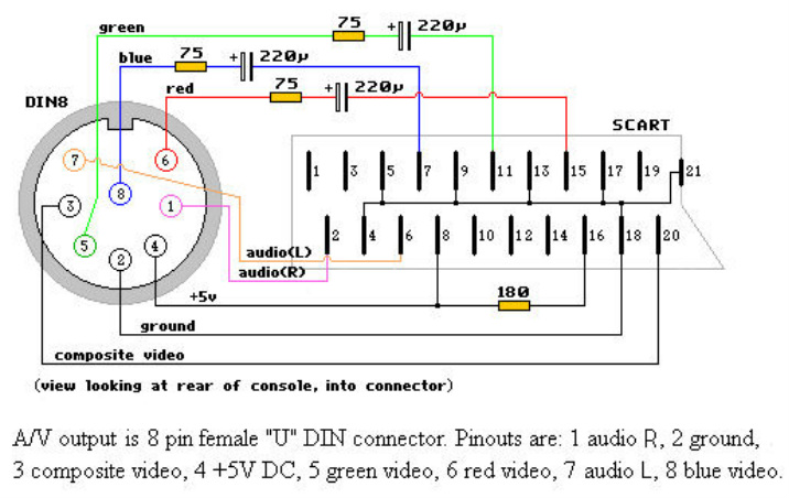
Sekä Playstation RGB Scart kaapelin. Tämä on helpompi ja halvempi yleensä hankkia, kuin erilliset osat. Siinä on valmiiksi Scart päässä tarvittavat vastukset. Kaava piuhalle on tällainen:
What you need: 8 pin DIN U/262 male connector (NOT C/270!), that connects to the Sega. Commodore 64 also uses the same connector, if you have one.
And Playstation RGB Scart cable. It usually is cheaper and more simple to get, than the separated parts. It already has the components in the Scart end. Here is the pinout for the cable:
VAROTUS! En oo vielä kerinny tehä tai testata tätä!!! /
WARNING! I have not done or tested this yet!!!
Ensinnäkin tarvitset:
8 pinnin uros DIN U/262 (EI C/270!) liittimen, joka menee Seegaan. Commodore 64:ssä on samanlainen, jos sattuu olemaan.
Sekä Playstation RGB Scart kaapelin. Tämä on helpompi ja halvempi yleensä hankkia, kuin erilliset osat. Siinä on valmiiksi Scart päässä tarvittavat vastukset. Kaava piuhalle on tällainen:
What you need: 8 pin DIN U/262 male connector (NOT C/270!), that connects to the Sega. Commodore 64 also uses the same connector, if you have one.
And Playstation RGB Scart cable. It usually is cheaper and more simple to get, than the separated parts. It already has the components in the Scart end. Here is the pinout for the cable:
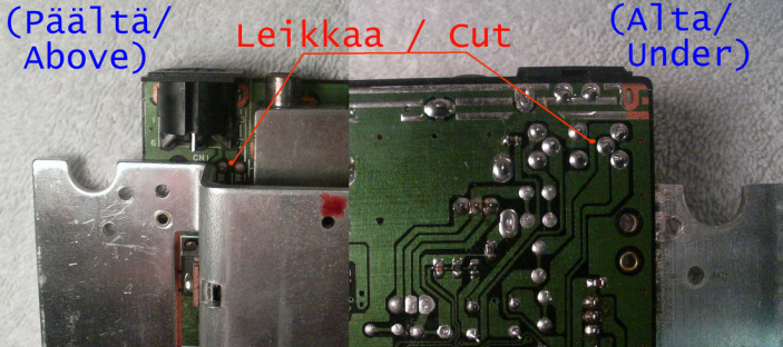
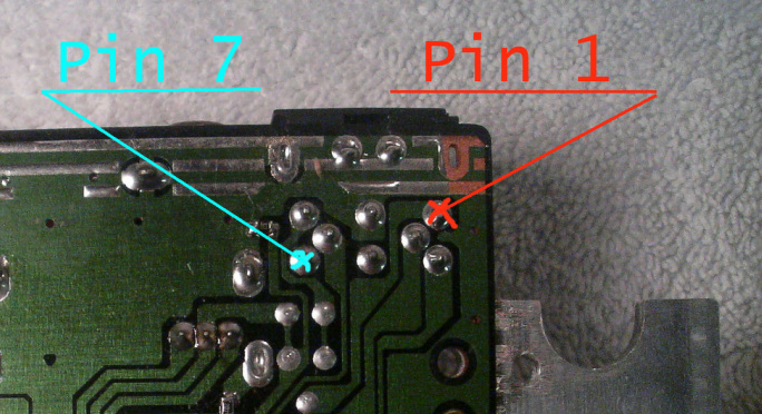
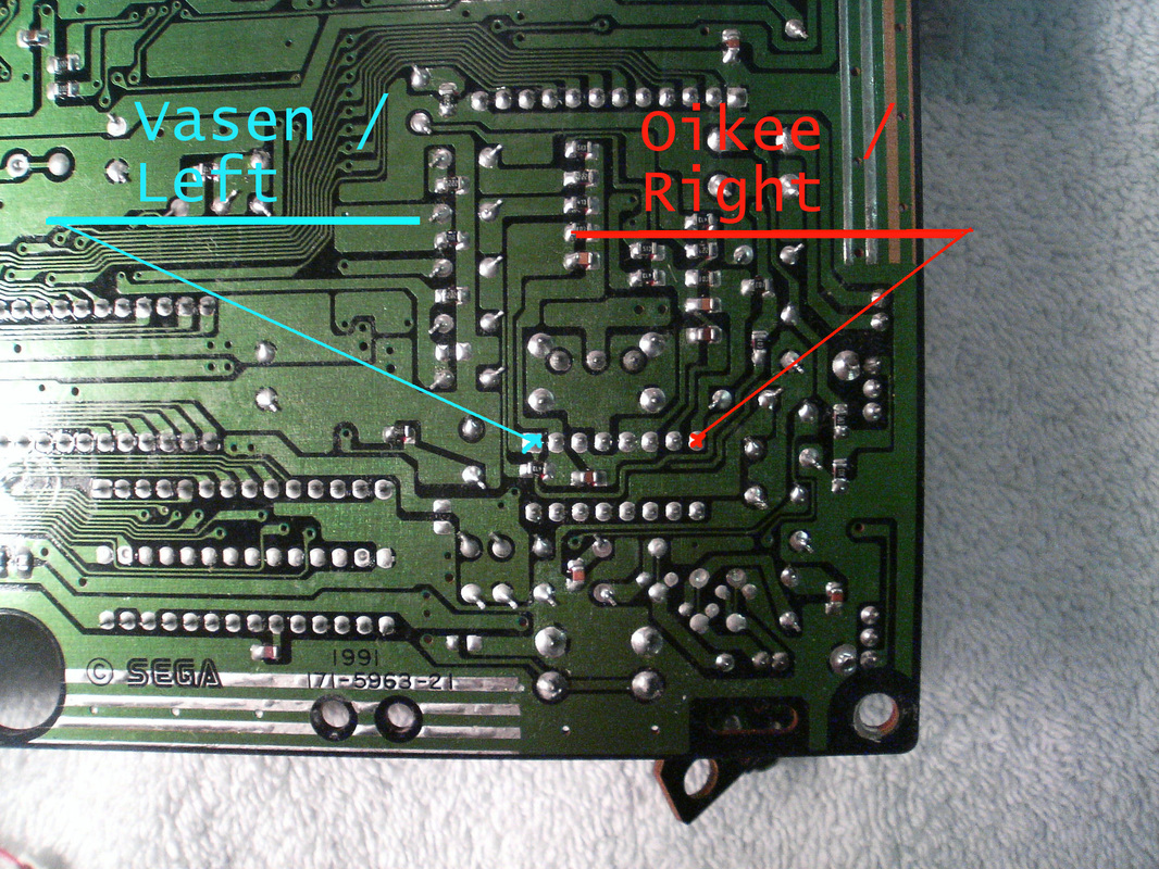
Lisäksi pitää emolevystä leikata kaksi reittiä poikki. Pinneiltä 1 ja 7. Reitti pin 1 on levyn alla. Ja 7 päällä. Näihin pisteisiin levyn alla, liitetään hyppylangat suoraan äänisirulta. Jonka voimakkuutta ei ole vahvistettu. Tarvittavat leikkaukset ja liitokset:
After that, cut the two trails for DIN female pins 1 and 7, from the motherboard. Trail for pin 1 is under the board. And 7 is above. To these points under the board, you need to add wires straight from the soundchip. Before its amplified. Here is what to cut and connect:
After that, cut the two trails for DIN female pins 1 and 7, from the motherboard. Trail for pin 1 is under the board. And 7 is above. To these points under the board, you need to add wires straight from the soundchip. Before its amplified. Here is what to cut and connect:
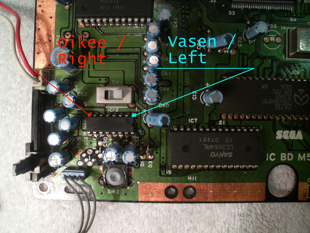
Äänisirun tunnistaminen emolevyn päältä (Virtakytkimen vieressä). /
Here is the soundchip on motherboard from above (near power switch).
Here is the soundchip on motherboard from above (near power switch).